Ejector pin marks are the small round impressions – sometimes raised, sometimes sunken, sometimes just a glossy ring – left where the ejector pins push the part off the core. Every moulded part has them somewhere. The question is whether they are visible, and whether they distort the part.
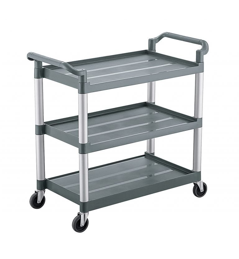
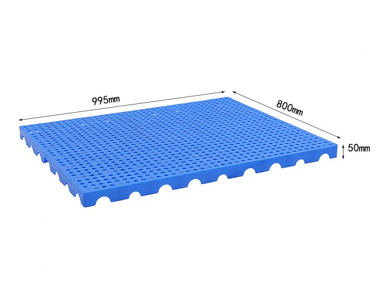
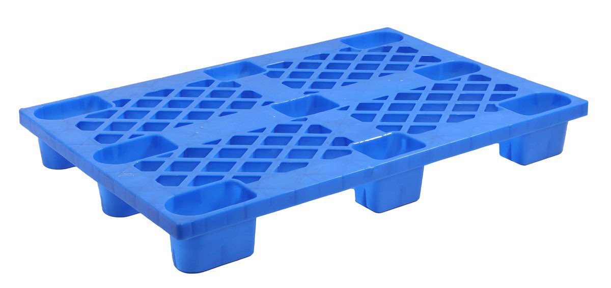
On a plastic pallet or a industrial crate they are invisible because they sit on a non-cosmetic face by design. On a food container or a hotel service cart panel they can scrap the part.
Raised vs sunken: they mean opposite things
| Mark type | What is happening | Direction to adjust |
|---|---|---|
| Raised bump | Pin pushes into a part that is still soft; material bulges out around the pin | Longer cooling time, or lower mould temperature |
| Sunken dent | Part shrinks onto the pin area; local sink because the section is thick | More holding pressure, longer hold time |
| Glossy ring only | Pin is flush but the surface texture differs | Usually acceptable – agree a limit sample |
| Stress whitening / crack | Pin force exceeds what the section can take at that temperature | More pins, bigger pins, or delay ejection |
| Part sticks and deforms | Not enough pins, or vacuum in a closed pocket | Add pins, add air poppet |
Fix 1 – Give the part more time to cool
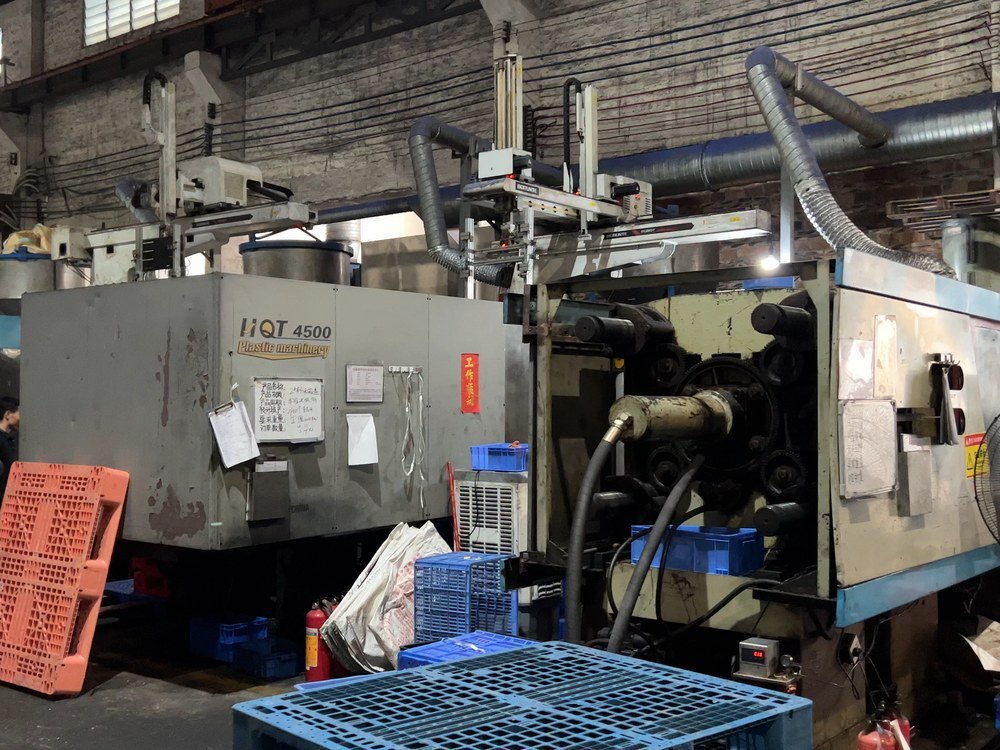
The most common cause of a raised mark is ejecting too early. The part looks solid on the surface but the core is still above the heat distortion temperature, so the pin simply dents it. Before you change anything else, add 2-3 seconds of cooling and re-check. On a 3 mm PP wall, ejection temperature should be below about 90 C; for ABS, below 80 C.
Fix 2 – Increase pin area, not pin force
Contact stress is force divided by area. Doubling the force on the same pin makes the mark worse. Doubling the pin area halves the stress. If the mark persists:
- Add pins – four small pins beat two large ones for even ejection
- Use a blade ejector or a stripper ring on a long wall
- Increase pin diameter from 4 mm to 6 mm where the wall allows
Fix 3 – Balance holding pressure
Sunken marks around pins are usually a local sink problem, not an ejection problem. The area under the pin is often the last to freeze, and if holding pressure stops too early the material pulls in. Extend hold time until the gate freezes – you can find that point by weighing parts at increasing hold times and taking the point where weight stops rising.
Fix 4 – Delay or stage the ejection
On a deep-draw part, ejecting in one fast stroke tends to jerk the part off the core. Staging – a slow 5 mm breakaway stroke, then full speed – reduces peak force and removes both the mark and the cracking. Most modern machines can do this from the control panel at no tooling cost.
Fix 5 – Move the pin
Sometimes the pin is simply in the wrong place. In a new tool review we ask three questions:
- Can the pin sit on a non-cosmetic face or under a rib?
- Is there enough steel around the pin to support it at injection pressure?
- Is the pin in a thick section that will sink regardless?
Moving pins is cheap at the design stage and expensive after the cavity is hardened. If you are developing a part, settle pin layout before the tool steel is cut – see how to select an injection moulding OEM for what to check at that stage.
Specification: what to put on the drawing
If pin marks matter on your part, write it down rather than relying on the molder’s judgement:
- Maximum acceptable pin mark depth (typically 0.05 mm on a cosmetic face)
- Pin locations not permitted on named surfaces
- Whether a raised or a sunken mark is acceptable – they usually are not both
- Viewing distance and light for inspection
Related: injection moulding hub, cost per part calculator.
Have a part with ejector marks you cannot get rid of? Send a photo and we will tell you which of the five fixes to try first.