Calculating injection molding clamp tonnage correctly prevents flash, short shots, and mold damage. The formula is: Clamp Force (tons) = Projected Area (cm2) x Material Factor (0.3 to 0.8) x Safety Factor (1.1 to 1.5). A part with 300 cm2 projected area molded in PP needs 300 x 0.5 x 1.2 = 180 tons. Undersizing causes flash and rejects; oversizing wastes machine capacity and increases cost per part.
What Is Clamp Tonnage in Injection Molding?
Clamp tonnage is the force an injection molding machine applies to keep the mold closed against injection pressure. During the injection phase, molten plastic enters the cavity at 600 to 1,800 bar. This pressure creates a separating force that tries to push the mold halves apart. If the clamp force is insufficient, the mold opens slightly and molten plastic escapes, producing flash. Too much clamp force wastes energy and can damage delicate molds.
For more on the overall injection molding process, see our injection molding hub. For part-level economics, our cost per part calculator shows how machine size affects pricing.
The Clamp Tonnage Formula
The standard formula for required clamp force is:
Clamp Force (tons) = Projected Area (cm2) x Material Factor (K) x Safety Factor (S)
Where:
- Projected Area — the shadow area of the part (including runner and gate) as viewed from the clamp direction, measured in square centimeters
- Material Factor (K) — depends on the plastic resin being molded, typically 0.3 to 0.8 tons/cm2
- Safety Factor (S) — accounts for viscosity variations, mold complexity, and process variables, typically 1.1 to 1.5
Material Factor Reference Table
Different plastics require different clamp forces due to varying melt viscosity and flow characteristics:
| Material | Material Factor (tons/cm2) | Typical Injection Pressure |
|---|---|---|
| PP (Polypropylene) | 0.5 | 600 to 1,000 bar |
| PE-HD (HDPE) | 0.4 to 0.5 | 600 to 1,000 bar |
| ABS | 0.5 to 0.6 | 800 to 1,200 bar |
| PS (Polystyrene) | 0.4 to 0.5 | 600 to 1,000 bar |
| PC (Polycarbonate) | 0.6 to 0.7 | 1,000 to 1,400 bar |
| PA (Nylon) | 0.6 to 0.8 | 800 to 1,400 bar |
| POM (Acetal) | 0.6 to 0.7 | 800 to 1,200 bar |
| GF-PP (Glass-filled PP) | 0.7 to 0.8 | 1,000 to 1,600 bar |
Step-by-Step Calculation Example
Example 1: Plastic Storage Container Lid (PP)
A round lid with 25 cm diameter has a projected area of pi x (12.5)2 = 491 cm2. Add the runner area of 9 cm2 for a total of 500 cm2.
Clamp Force = 500 x 0.5 (PP) x 1.2 (safety) = 300 tons
Example 2: Thin-Wall Food Container (PP)
A rectangular food container 15 x 10 cm has a projected area of 150 cm2. Thin-wall parts need higher injection pressure, so use a safety factor of 1.5.
Clamp Force = 150 x 0.5 x 1.5 = 113 tons
Example 3: Engineering Part with Glass-Filled Nylon
A bracket with projected area 80 cm2 in glass-filled PA66:
Clamp Force = 80 x 0.8 x 1.3 = 83 tons
Factors That Affect Required Clamp Force
Wall Thickness
Thinner walls require higher injection pressure to fill the cavity before the melt freezes. Thin-wall parts (under 1 mm) may need 2 to 3 times the clamp force of standard parts with the same projected area. Use a safety factor of 1.5 to 2.0 for thin-wall applications.
Flow Length to Thickness Ratio
When molten plastic travels a long distance through a thin section, the required injection pressure rises. A flow length to thickness ratio above 200 typically requires higher clamp force. Mold flow analysis software can predict pressure losses more precisely than manual calculations.
Mold Design Complexity
Multi-cavity molds, hot runner systems, and complex core structures all affect pressure distribution. A 4-cavity mold does not simply multiply single-cavity clamp force by 4; the runner system adds projected area and the interaction between cavities can reduce or increase total force depending on layout.
Melt Temperature and Viscosity
Higher melt temperatures reduce viscosity and lower injection pressure, which reduces required clamp force. However, higher temperatures increase cycle time and energy cost. Finding the optimal melt temperature is a process engineering decision that affects both quality and cost.
What Happens When Clamp Tonnage Is Wrong
Too Low: Flash and Defects
Insufficient clamp force lets the mold open by 0.02 to 0.1 mm during injection. Molten plastic escapes at the parting line, creating flash. Flash requires secondary trimming, increases scrap rate, and can damage the mold parting line over time. Flash is the most common symptom of undersized clamp force.
Too High: Mold Damage and Energy Waste
Excessive clamp force compresses the mold beyond its design limits. This can crush vents, distort parting lines, and accelerate mold wear. It also wastes energy and ties up larger machines that could run bigger molds, increasing cost per part. For a detailed QC approach, see our quality control inspection guide.
Machine Selection: Matching Tonnage to Part
Selecting the right machine means balancing clamp force availability with shot size, platen size, and tie-bar spacing. A 300-ton machine may have the right clamp force but insufficient platen area for a large part. Always verify:
- Clamp force exceeds calculated requirement by at least 10 percent
- Shot size fills 30 to 80 percent of barrel capacity
- Platen dimensions accommodate the mold base
- Tie-bar spacing allows mold installation
- Opening stroke provides sufficient ejection clearance
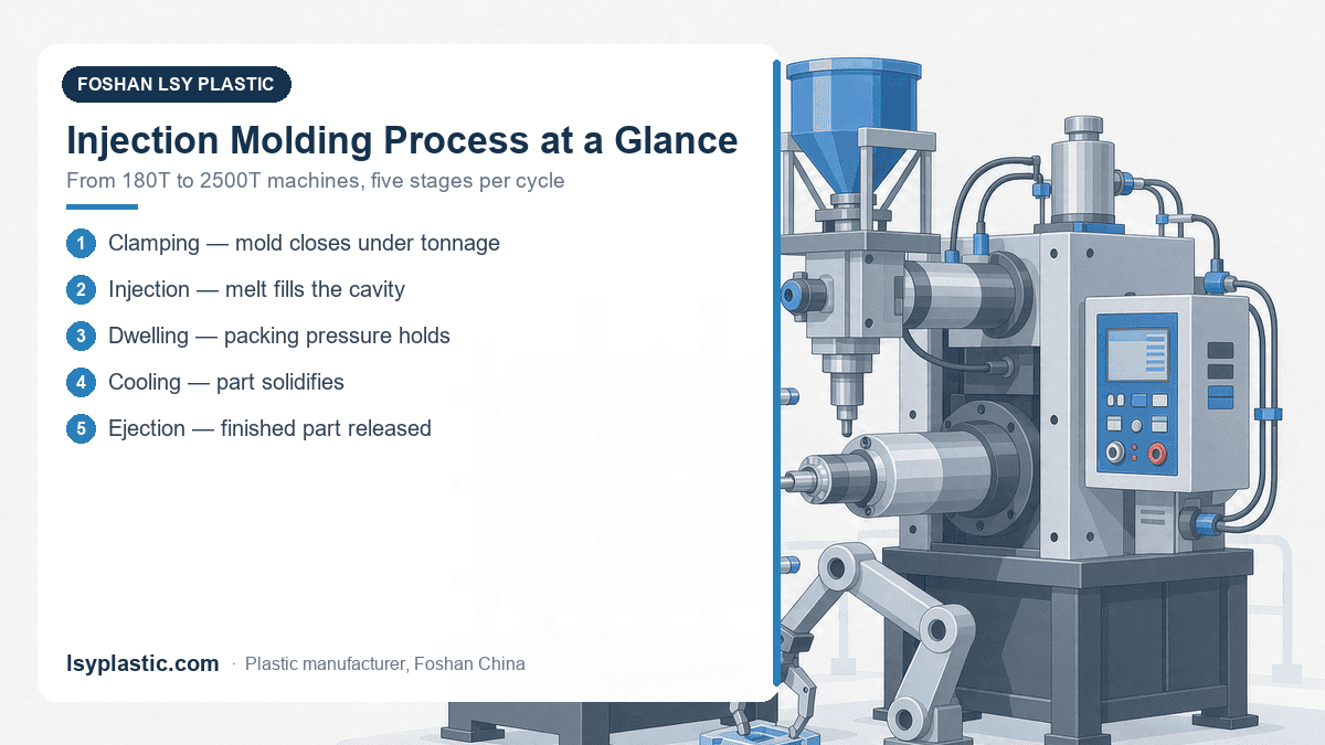
LSY Plastic operates injection molding machines from 180T to 2500T (JSW, Mitsubishi, NSC) and handles clamp force calculations as part of our OEM service. For buyers sourcing custom-molded parts from China, our OEM buying guide walks through the entire process.
Conclusion
Injection molding clamp tonnage calculation is a straightforward but critical step. The formula is projected area times material factor times safety factor. Getting it right prevents flash, protects molds, and ensures efficient machine utilization. When in doubt, use mold flow analysis and consult with your molder. A 20 percent safety margin is standard practice for production reliability.
LSY Plastic provides full-service injection molding from mold design to production, with machines ranging from 180 to 2,500 tons clamp force. Our engineering team handles tonnage calculations, mold flow analysis, and process optimization. Contact us for your next project.
Get a quote today: WhatsApp +86 19311059570 | Email fstyx01@lsyplastic.com
Need reliable custom injection molded parts? Browse the OEM and ODM injection molding services collection and request a quote.
Frequently Asked Questions
What is the clamp tonnage formula?
Clamp Force (tons) = Projected Area (cm2) x Material Factor (0.3 to 0.8) x Safety Factor (1.1 to 1.5). For example, a part with 300 cm2 projected area moulded in PP needs 300 x 0.5 x 1.2 = 180 tons.
What happens if the clamp tonnage is wrong?
Undersizing causes flash, short shots and mould damage; oversizing wastes machine capacity and raises cost per part. Correct tonnage keeps the mould closed against injection pressure without over-clamping.
What affects the required clamp force?
Projected part area, material flow behaviour, wall thickness, gate design and the required safety margin. Materials that flow easily need a lower factor, while thicker or stiffer parts need more clamp force.
How does LSY match tonnage to a part?
LSY runs Japanese machines from 180T to 2500T and calculates clamp tonnage per part during design-for-manufacture review, so the mould runs on the right machine for consistent quality. Samples at cost price; overseas orders ship FCL.