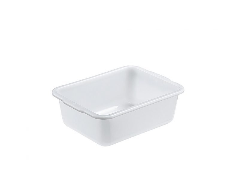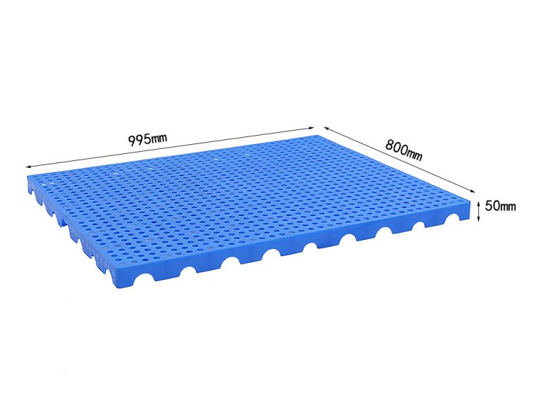
Warpage is the defect that turns up at assembly rather than at the moulding machine. The part measures fine on the bench, but it rocks on a flat surface, a lid will not sit square, or a pallet deck will not sit flat on a rack beam.
Warpage is not a mystery – it is shrinkage that happened unevenly. Once you know which of the four mechanisms is driving it, the fix is usually obvious.
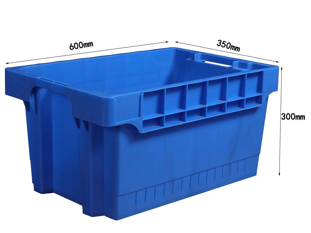
The four mechanisms
1. Differential shrinkage (thickness variation)
Thick sections shrink more and cool later. If one side of a panel is thicker, that side ends up shorter and the part curls toward it. This is the same root cause as sink marks and the same rule fixes it: keep wall thickness uniform, or core out thick pads.
2. Uneven cooling
The cavity side and the core side rarely run at the same temperature. If the core runs hotter, the face against the core shrinks more after ejection and the part bows toward the core. A 10-15 C difference between the two halves is enough to bow a flat panel visibly.
Check: measure both halves with a contact thermometer during a steady run, not at start-up.
3. Fibre orientation (filled materials)
Glass fibres align with flow. Shrinkage along the fibre direction is roughly a third of shrinkage across it. On a glass-filled part this anisotropy dominates everything else, and it is why a 30% GF part warps in a direction that looks arbitrary. The usual fix is to change the gate – gating at the centre of a round part instead of the edge switches the flow pattern from radial to uniform and often halves the warp.
4. Orientation and residual stress
Molecular orientation frozen into the part during fast filling relaxes later, especially if the part sees heat in service or transport. A container that sits flat in the factory and bows after a hot container journey is relaxing residual stress. Annealing, or slower fill, is the fix.
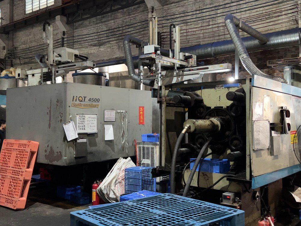
Controls that work
| Mechanism | Process control | Design control |
|---|---|---|
| Thickness variation | Longer cooling, higher hold | Uniform wall; core out pads |
| Uneven cooling | Balance the two halves within 5-10 C | Add cooling to the hot side |
| Fibre orientation | Lower injection speed; raise mould temp | Move gate; add ribs in flow direction |
| Residual stress | Slower fill; anneal at 80-100 C for 1-2 h | Avoid sharp corners; use radii |
Design rules that hold flatness
- Keep wall thickness uniform – every thickness change is a warp risk
- Use ribs instead of thick walls – a ribbed panel is stiffer and warps less than a thick flat one; ribs also give you a place to hide sink
- Gate at the geometric centre for flat round or square parts
- Add a flange or a rolled edge on long flat panels – a 10 mm flange on a 600 mm panel does more for flatness than any process change
- Avoid long unsupported flat spans – anything over about 300 mm of flat wall needs ribs or a slight crown
How to measure it
Do not measure warpage by eye on a granite table alone. The practical method:
- Place the part on a flat surface in the orientation it will be used
- Measure the gap with a feeler gauge at the four corners and the centre
- Repeat after 24 hours – parts continue to move as they fully stabilise
- For a specification, state the maximum gap over a stated length (for example 1.5 mm over 600 mm)
The 24-hour check matters. A part that measures flat one hour after moulding can move overnight, and if your assembly line is two days downstream you will find out the hard way.
Flatness and load-bearing parts
For racked pallets and stackable containers, warpage is not cosmetic – it changes how load transfers. A pallet deck that bows 3 mm in the middle will not sit properly on a rack beam and will creep under load. If your part carries load, specify flatness as a functional dimension, not a cosmetic one, and test it under load rather than on a bench.
Related: injection moulding hub, HDPE vs PP comparison, pallet test standards ISO 8611.
Parts arriving bowed, or a flatness problem in a new design? Send the drawing and the measured gap and we will tell you which mechanism is likely driving it.