
The cheapest way to cut injection molded part cost is usually to make the part thinner and rib it. Wall thickness drives cooling time, cooling time drives cycle time, and cycle time drives almost everything else — machine occupancy, labour, energy and scrap. This guide explains where cost actually sits in a moulded part, the wall thickness ranges that work for common materials, and the rib, boss and draft rules that add stiffness without adding weight, sink marks or warpage. It is written for buyers and product engineers briefing a factory, and pairs with our guide to injection mold tooling cost factors.
Where the cost of a molded part actually sits
| Cost driver | Share of unit cost | What changes it |
|---|---|---|
| Machine time | Often the largest single line | Cycle time, tonnage, cavitation |
| Material | Significant but rarely dominant | Wall thickness, part volume, regrind policy |
| Labour and handling | Moderate to high | Automation, degating, assembly steps |
| Tooling amortisation | Depends on volume | Cavitation, tool life, steel grade |
| Scrap and defects | Small per unit but adds up fast | Warp, sink, short shots, flow lines |
Because machine time dominates, the productive conversation is not “where can we use cheaper resin” but “how do we get the part out of the mould faster and with fewer rejects”. Wall thickness and rib design are the two levers with the largest effect on both.
Wall thickness: the square-law that decides cycle time
Cooling time scales roughly with the square of wall thickness. Going from 2 mm to 4 mm does not double cooling — it roughly quadruples it. A part that runs on a 25 second cycle can jump to 60 seconds or more, which is why adding thickness to solve a stiffness problem is almost always the wrong answer.
| Material | Typical wall range | Notes |
|---|---|---|
| PP | 1.5 to 3.0 mm | Excellent flow; long parts can run thinner with good gating |
| HDPE | 1.5 to 4.0 mm | Higher shrink, more warpage risk on flat panels |
| ABS | 1.8 to 3.5 mm | Good surface finish; thicker walls sink visibly |
| PC | 2.0 to 3.5 mm | High viscosity; needs generous flow paths |
| Glass-filled PP, PA | 1.5 to 3.0 mm | Stiffer, but anisotropic shrink requires flow analysis |
Keep the wall uniform
The single most important wall rule is consistency. A uniform wall cools evenly and shrinks evenly. Where thickness must change, transition gradually — a taper over at least three times the thickness difference, rather than a step. Abrupt thickness changes produce the shrink-related defects that scrap parts.
Rib design: stiffness at a fraction of the material
A rib adds bending stiffness far more efficiently than extra wall thickness, because stiffness rises with the cube of section depth while material use rises linearly with thickness. That is the whole case for ribbing a part.
The classic rules:
- Rib thickness: 50 to 60% of the adjoining wall. Thicker ribs attract material, cool last and pull a sink mark into the visible face.
- Rib height: up to about three times the wall thickness. Beyond that, the rib tends to warp and adds little further stiffness.
- Rib spacing: at least twice the wall thickness centre to centre, so the mould steel between ribs can be cooled properly.
- Draft: 0.5 to 1° per side on ribs, more for deep or textured ribs, so parts release without scuffing.
- Base radius: a fillet of 0.25 to 0.5 times wall thickness where the rib meets the wall, to avoid a stress concentration and to help material flow.
Rib layout, not just rib size
Rib direction should follow the bending load. A panel that flexes across its width needs ribs running across that direction. Cross-ribbing in two directions adds stiffness but also adds a second shrink direction, which increases warpage risk; use it only where stiffness genuinely requires it and confirm with a flow analysis.
Where appearance matters, put ribs on the hidden face. If they must be on the visible face, reduce rib thickness to 40 to 50% of wall and increase the number of ribs rather than thickening each one.
Bosses, corners and draft
Bosses (for screws or inserts) are thick features and are the second most common cause of sink marks. Keep the boss wall at 50 to 60% of the main wall, add ribs to the boss rather than growing its diameter, and leave a gap to the nearest wall of at least 0.25 times the wall thickness.
Corners should be radiused on both the outside and inside surfaces, with the inside radius smaller than the outside radius so the wall stays uniform. Sharp internal corners concentrate stress and are where cracked parts originate.
Draft is not optional. Even 0.5° per side changes ejection force dramatically on textured parts. Textured surfaces typically need 1 to 1.5° per side, and moulds that are grit-blasted after drafting require re-checking.
Worked example: ribbed versus thick wall
Consider a 400 x 300 mm crate base panel. Option A is a 3.5 mm solid wall. Option B is a 2.2 mm wall with a rib grid at 55% of wall thickness.
| Measure | A: 3.5 mm solid | B: 2.2 mm ribbed |
|---|---|---|
| Relative stiffness in bending | Baseline | Higher |
| Material per part | Baseline | Roughly 20 to 30% lower |
| Cooling behaviour | Slow, higher warpage risk | Faster, more uniform |
| Cycle time | Longer | Shorter |
| Visible face quality | Good | Good if ribbing is on the hidden face |
This is why well-designed crates, pallets and bins use rib structures rather than solid sections. Ribbing is not a cost compromise — it is usually the better engineering answer as well.
How to brief your moulding factory
- Send a 3D model or a detailed drawing with the load case, not just a shape.
- State the required stiffness or load at a defined deflection — “must not bow more than 5 mm under 300 kg” is more useful than “make it strong”.
- Ask for a DFM report listing wall thickness, rib proportions, draft, gate position and expected warp risk.
- Request a flow analysis where the part is large or flat, since flat panels warp most.
- Agree the material grade and regrind policy in writing before tooling is cut.
Regrind deserves a mention: reused material lowers resin cost, but regrind changes shrink and reduces impact strength. A workable policy caps regrind content — often 15 to 25% for non-critical parts and zero for food contact layers or strength-critical sections.
Design and tooling from one factory
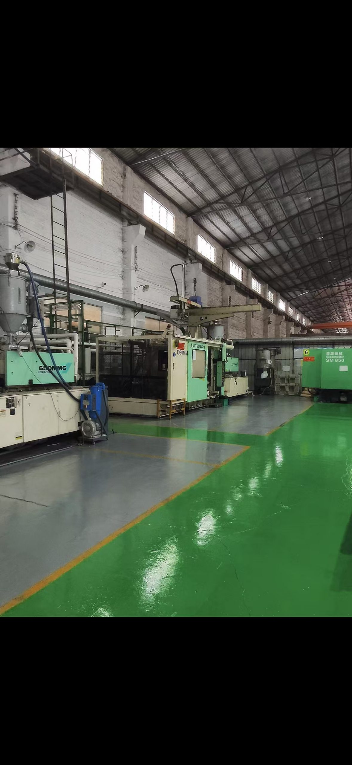
LSY Plastic has molded industrial and hospitality plastic products since 1991 from our Foshan factory, with Japanese imported injection machines from 180T to 2500T and our own mould workshop. Because design review, tooling and production happen under one roof, DFM feedback comes back before the mould is cut rather than after the first samples fail.
Our OEM and ODM process is described in the custom plastic injection molding guide. We supply OEM customers including BYD, OPPO, vivo and Delice, and hold a 20,000 m² warehouse for repeat orders.
Send a drawing for a DFM review
Send a 3D model or drawing with the load case, annual volume, target material and any food-contact or ESD requirement. We will return a DFM report covering wall thickness, rib layout, draft, gate position, estimated cycle time, tooling cost and unit price.
WhatsApp: +86 19311059570
Email: fstyx01@lsyplastic.com
Related reading: how much does a plastic injection mold cost, plastic pallet materials HDPE vs PP, and our factory.