Every moulded part carries the signature of the process that made it. When a pallet deck sinks, a crate warps or a cover flashes, the defect is not random — it is the visible end of a decision made in holding pressure, cooling time, gate position or wall thickness. On a shop floor running presses from 180 to 2,500 tons, the same ten defects account for almost every rejected part, and each one has a first fix that usually works.
Read the defect before you touch the machine
The instinct on seeing a bad part is to adjust the press. Half the time the press is innocent — the tool has no venting, the wall section is too thick, or the material is damp. Working through process, then tool, then material, then design, in that order, saves the hours that get wasted chasing a parameter that was never the cause.
The ten defects and their first remedies
1. Sink marks
Sign: a shallow depression on a flat surface, usually opposite a rib or a thick boss.
Cause: the thick section cools last and pulls material inward as it shrinks.
Remedy: increase holding pressure and hold time first. If the mark persists, the section is too thick — rib thickness should sit at roughly 50–60% of the nominal wall. No amount of pressure fixes a rib that is over-designed.
2. Warpage
Sign: the part does not sit flat; corners lift.
Cause: differential cooling — one face froze before the other, or the packing was uneven across the cavity.
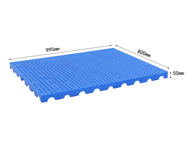
Remedy: balance the cooling circuit and extend cooling time before touching anything else. On large flat parts like pallet decks and crate bases, mould temperature differential is the usual culprit.
3. Flash
Sign: a thin fin of plastic along the parting line or around ejector pins.
Cause: melt forced into the parting line gap — clamp force too low for the projected area, or a parting line that has worn or been damaged.
Remedy: check clamp tonnage against projected area first. If the tonnage is correct, the tool needs the parting line re-seated. Running a damaged tool at higher clamp force damages the tool faster.
4. Burn marks (diesel effect)
Sign: small brown or black scorched patches, typically at the end of fill or in a deep rib.
Cause: trapped air compressed so fast it heats to the point of burning the melt — a venting failure, not a temperature failure.
Remedy: add or clean vents at the last point of fill; reduce injection speed in that final phase. Raising melt temperature makes it worse, which is how this one gets misdiagnosed.
5. Weld lines (knit lines)
Sign: a visible line where two melt fronts met, often weaker than the rest of the part.
Cause: flow fronts cooling before they fuse — around holes, cores or multi-gate fills.
Remedy: raise melt and mould temperature and slow the fill slightly to keep the fronts hot. If strength at the line matters, move the gate so the line lands somewhere it carries no load.

6. Short shot
Sign: the cavity is not filled; the part is incomplete.
Cause: insufficient shot volume, flow restriction at the gate, or material freezing off early in a thin section.
Remedy: check shot size and cushion first, then gate size. Increasing pressure alone will pack an already-frozen flow path and produce flash elsewhere.
7. Flow lines
Sign: wavy streaks radiating from the gate on an otherwise glossy surface.
Cause: the melt front cooled unevenly as it advanced.
Remedy: raise melt temperature and injection speed so the front stays hot; enlarging the gate helps on large parts.
8. Jetting
Sign: a squiggle of material on the surface where the melt entered.
Cause: melt shooting into open cavity space instead of hugging a wall — a gate geometry problem.
Remedy: change to a fan or overlap gate so the melt contacts a wall immediately, or reduce injection speed through the gate.
9. Ejector pin marks
Sign: round witness marks, sometimes with stress whitening or a pushed-through boss.
Cause: ejection before the part has cooled enough, or too few pins carrying the load.
Remedy: extend cooling time, then add pins or increase pin area. Polishing the cavity to make release easier is treating the symptom.
10. Voids and bubbles
Sign: internal voids in thick sections, or surface blisters.
Cause: trapped air or moisture, or shrinkage uncompensated by holding pressure in a thick section.
Remedy: dry the material first — hygroscopic resins are the most common source of bubbles. Then raise holding pressure and check the gate has not frozen off before the part is packed.

The four defects that come back as warranty claims
Of the ten, four account for most of what a customer actually complains about after delivery: warpage (the part will not stack or the lid will not seat), sink marks (visible on a cosmetic face), weld lines at a loaded corner (the part cracks in service), and flash (the part will not assemble or has a sharp edge). These are the ones worth catching at sampling rather than at goods-in.
Design decisions that prevent defects before tooling
Uniform wall thickness, ribs at 50–60% of nominal wall, generous radii at corners, and gate positions that keep weld lines away from loaded areas cost nothing at the drawing stage and save a tool modification later. A mould workshop that reviews the drawing before cutting steel is worth more than a fast quote.
FOSHAN LSY Plastic has run its own mould workshop alongside its injection shop for three decades, which is why defect correction usually happens on the drawing or in the tool rather than being negotiated away with the customer. Export orders ship as full container loads; samples are charged at cost. Domestic orders carry no minimum quantity.
FAQ
Which defect is most common on large flat parts?
Warpage. Large flat surfaces — pallet decks, crate bases, tray bottoms — cool unevenly unless the circuit is balanced, and the resulting differential shrinkage lifts corners. Balanced cooling and adequate cooling time prevent most of it.
Can burn marks be fixed by lowering the melt temperature?
Occasionally, but it is the wrong first move. Burn marks are compressed trapped air, so the fix is venting at the last point of fill. Lowering temperature reduces the symptom while leaving the cause, and risks short shots elsewhere.
Why does a part look fine on the press and warp overnight?
Because it was ejected before the core was fully cooled. The part held shape while warm and relaxed afterwards as the residual stress released. Extend cooling time, and check that the part is supported after ejection.
Related guide: knit lines and weld lines in injection molding.
Related guides:
Injection Molding Burn Marks: Causes & Fixes
Ejector Pin Marks: Why They Show & How to Fix
Sink Marks in Injection Molding: Causes & Fixes
Injection Molding Flash: Causes, Fixes & Limits
Injection Molding Warpage: Causes & How to Control